If you know me at all, and you probably do not, dear reader, you would know I have an affinity for houseplants. Plants of all kinds, really, and I very much enjoy collecting rare species and admiring their beauty. The one thing, however, I do not enjoy is watering them. I have been dreaming of an automated system for quite some time - the ability to just press a button, or not press anything at all, and have my little beauties sparkling green with minimal effort.
This was my first experiment with microcontrollers of any kind and automation beyond the digital realm. My scheming eventually brought about this lovely journey through a world I am wholly unfamiliar with. Join me on my quest to never touch a watering can again.
Materials
Below is everything I used, sourced from Amazon. An important note: bulk purchase all of the boards, but especially the ESP32. These little things crap out constantly, and it is very handy to have another ready to flash at a moment's notice.
- 50FT Garden Watering System with 16 Nozzles, 5/16 inch Hose
- 12V Power Supply, 110V AC to 12V 2A DC, 5.5/2.1mm DC Connector
- ESP32 ESP-32S Development Board 2.4GHz Dual-Mode WiFi + Bluetooth
- 12V Mini Food Grade Self-Priming Diaphragm Pump, 1.3LPM
- 10 Pack LM2596 DC-DC Buck Converter Step Down Module, 1.25V–30V 3A
- 4 Channel 5V Relay Module with Optocoupler, High or Low Level Trigger
- Arduino breadboard, jumper wires, assorted chaos
Shopping List
Everything below is what I used. Prices are approximate at time of writing. The ESP32 and buck converter especially - buy multiples. You will need them.
| Item | Notes | Price | Link |
|---|---|---|---|
| ESP32 ESP-32S Dev Board | Buy a pack of 3+. They crap out. | ~$18/3pk | Amazon |
| LM2596 Buck Converter (10pk) | 12V to 5V step-down. Having spares saved me. | ~$12 | Amazon |
| 4 Channel 5V Relay Module | Optocoupler, high/low trigger. Label your terminals. | ~$8 | Amazon |
| 12V 2A Power Supply | 5.5/2.1mm barrel jack. Get one with screw terminals. | ~$10 | Amazon |
| 12V Mini Diaphragm Pump | 1.3LPM, food grade, self-priming. Do not run dry. | ~$12 | Amazon |
| 50FT Drip Irrigation Kit | 5/16" hose, 16 adjustable nozzles. More than enough. | ~$15 | Amazon |
| Soldering Iron (adjustable) | 60W adjustable. Non-negotiable. Buy it first. | ~$20 | Amazon |
| 60/40 Rosin Core Solder, 0.8mm | Not lead-free. Your life is hard enough already. | ~$8 | Amazon |
| Solder Wick | For when you inevitably swap VIN+ and VIN-. | ~$5 | Amazon |
| PTFE Tape | Wrap all barb connections. Prevents leaks. | ~$3 | Amazon |
Phase 1: Blink
After gathering all my materials, I started with the classic beginner sketch - blink. If you can make an LED blink, you can make a relay click, and if you can make a relay click, you can make a pump run. The relay toggle sketch below was my first real win of the project.
const int relayPin = 26;

void setup() {
  pinMode(relayPin, OUTPUT);
  digitalWrite(relayPin, HIGH); // relay off at start
}

void loop() {
  digitalWrite(relayPin, LOW);  // relay ON
  delay(2000);
  digitalWrite(relayPin, HIGH); // relay OFF
  delay(2000);
}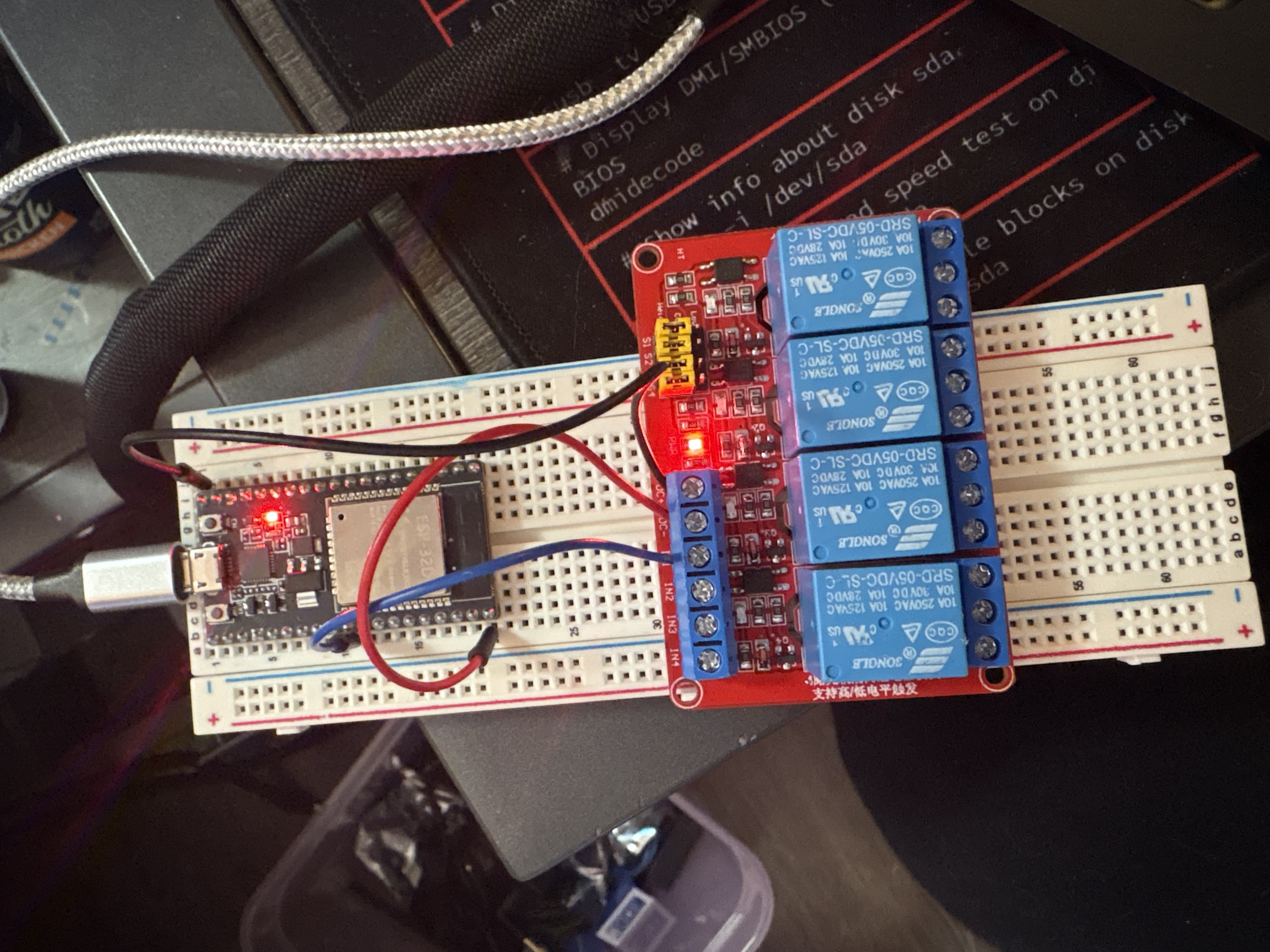
You should hear a satisfying click every two seconds and see the indicator LED on the relay module toggle. If you do not hear a click, keep reading - I have been exactly where you are.
Phase 2: The Iron Throne
I spent a full day experimenting with my materials. After that day, and much frustration - electrical tape is the worst, seriously - I decided to buck up and purchase a soldering iron. Best decision I made in this entire project, possibly in my life. My multimeter I ordered was broken out of the box, which was a delight to discover mid-testing. Womp womp. I used the brightness of the onboard LEDs to estimate voltage instead, which is exactly as scientific as it sounds.
The next day, I soldered everything together. I started with the buck converter, and mistakenly swapped the VIN+ and VIN- holes. Removing solder is not as easy as they make it seem - some copper solder wick and very pointy tweezers eventually got the job done. Sometimes adding a little more solder to the pad first helps it flow out more cleanly. Once corrected, I tinned all wire ends before every connection. Here is the full wiring layout:
Wiring
- 12V Adapter (+) → bundle: relay COM + buck VIN+
- 12V Adapter (−) → bundle: buck VIN− + pump black
- Buck VOUT+ → relay DC+
- Buck VOUT− → relay DC− (shared with ESP32 GND)
- Relay COM → 12V positive bundle
- Relay NO → pump red wire
- Relay IN → ESP32 GPIO 23 (jumper wire, not soldered)
- ESP32 5V → buck VOUT+ (powers ESP32 from the 12V adapter)
- Pump red → relay NO
- Pump black → 12V negative bundle
Do not connect both USB and the buck converter to the ESP32 5V pin simultaneously. Wires will overheat immediately. One power source only. Ask me how I know.
Once everything was soldered and the 12V adapter was plugged in, both the buck converter and relay LEDs lit up. Promising. I set up a basic sketch, confirmed the relay was clicking from the ESP32 signal, and wired in the pump. And then nothing moved.
No Terminals
The LEDs lit up. The relay audibly clicked. The pump did not run. A direct 12V bypass confirmed the pump itself was fine. I tried bumping the buck converter potentiometer up slightly - turns out it was set too low to fully energize the relay coil, and a small adjustment fixed the click. But still no water.
I moved from channel 1 to channel 2 to channel 3, suspecting bad NO terminals across the board. This seemed statistically unlikely in hindsight, but I was committed to the bit. Eventually I bridged COM to NO manually with a spare wire while the relay was active, and the pump ran perfectly. The relay was switching - the circuit just was not completing through the terminal screws.
The actual problem, which I discovered only after considerable humiliation, was that I had been reading the terminal numbering from the wrong side of the board. I thought I was plugged into channel 3. I was in channel 2. The IN pin I had wired was controlling a completely different channel than the COM and NO terminals I was using. I have since taped the correct numbering onto the board. Learning is a process. Discovering you have been overcomplicating something very simple is always slightly humiliating.
Throughout this project I learned to pay very close attention to LEDs. The buck converter's light only shining when I adjusted the voltage. The beautiful blinking of a properly wired relay. I feel like Gatsby with his green light, calling out across the vast blackness of the cold, unflinching sea.
Once the correct channel was wired to the correct IN pin, the relay clicked, the pump ran, and water flowed. Here is the basic timer sketch I used for initial testing:
#define RELAY_PIN 23

void setup() {
  Serial.begin(115200);
  pinMode(RELAY_PIN, OUTPUT);
  digitalWrite(RELAY_PIN, LOW);
  Serial.println("Plant watering system ready!");
}

void runPump() {
  Serial.println("Running pump...");
  digitalWrite(RELAY_PIN, HIGH);
  delay(5000); // 5 seconds
  digitalWrite(RELAY_PIN, LOW);
  Serial.println("Pump done!");
}

void loop() {
  runPump();
  Serial.println("Waiting 3 days...");
  delay(259200000); // 72 hours
}
The Scorch Trials
Before gluing the buck converter down, the VIN+ wire pulled out of the soldered hole. I fought with it for about an hour. I could not get a clean enough connection and was starting to worry I had lifted the pad. I had spares, so I rewired everything onto a fresh buck converter. Whether the original was fine or I had damaged it, I will never know. Ignorance is occasionally a gift.
Once everything was glued down and the full unit was powered on with 12V, it turned on, cycled off, and started buzzing. After a few more test runs the pump stopped working entirely. Spectacular. The pump had been run dry too many times during testing and lost its prime. Once I got water into the intake tube and let it fully prime, everything came back to life.
This pump has a self-priming function but do not abuse it. Running it dry repeatedly will kill it, or at minimum give it a very bad afternoon.
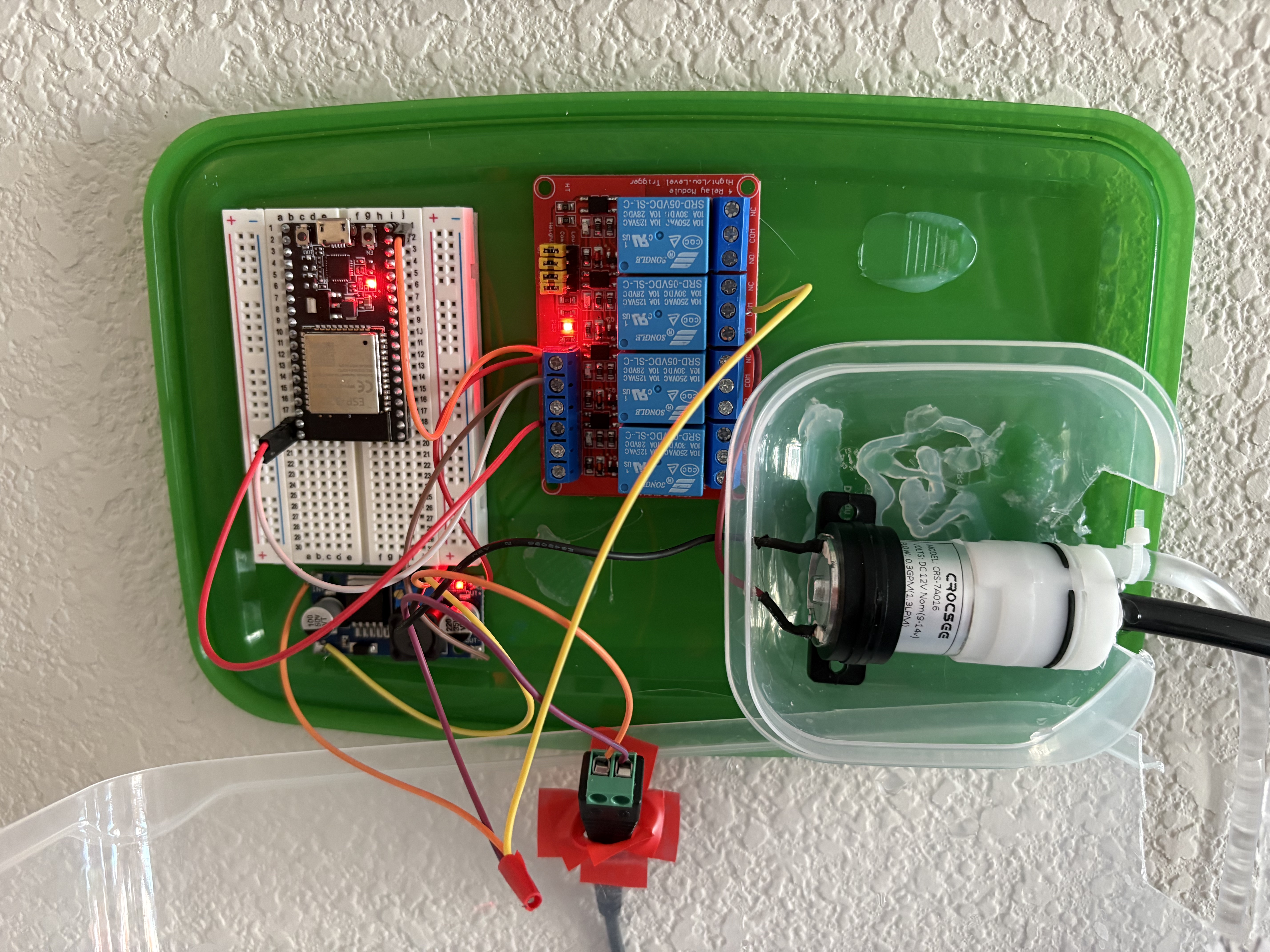
The Tupperware Chronicles
For housing, I used a large IKEA tupperware I already had. It needed to be as watertight as possible to keep water away from the boards. The pump itself was the bigger leak risk, so I went with tupperware inside tupperware - a nested containment strategy that I am choosing to call intentional. I drilled holes for the wires and pump nozzles on both sides using a spiral bit slightly larger than each component's diameter.
Be careful drilling plastic - it can crack under heat and pressure. Use slow speed and light pressure. Safety glasses always. I used a hammer to brace the container so my hand was nowhere near the bit.
IoT Network + NTP
I wanted HAL's Garden on my IoT subnet, which runs on my home intranet. The intranet does not have internet access - long story involving an ethernet terminal in my apartment that was never properly set up. No internet means no public NTP servers, which means the ESP32 has no way to know what time it is after a reboot. Without a time source, scheduled watering becomes "runs whenever it feels like it," which defeats the entire point.
The fix was to run a local NTP server on my Proxmox homelab. I created a new LXC container using the Alpine Linux template. Alpine is perfect for this - the whole thing runs on 64MB of RAM and a tiny slice of CPU. The container only needs to do one thing: run chrony and answer NTP requests from the IoT VLAN.
The slightly annoying part was networking. My Proxmox node has a single physical NIC, and my VLANs are handled by a managed switch. To get the Alpine container onto the IoT VLAN properly, I set up a VLAN-aware Linux bridge on the Proxmox host (vmbr0) and attached the container's virtual NIC to that bridge with the correct VLAN tag. This way the container gets a real IP on the IoT subnet and the ESP32 can reach it directly, no routing tricks needed.
In Proxmox, the container network config looks like this:
# Proxmox container network config (in the CT's Options > Network)
# Bridge: vmbr0
# VLAN Tag: [your IoT VLAN ID]
# IP: static IP on your IoT subnet, e.g. 192.168.0.108/24
# Gateway: your IoT gateway
On the Proxmox host itself, make sure your bridge is VLAN-aware. In /etc/network/interfaces:
auto vmbr0
iface vmbr0 inet static
    address YOUR_PROXMOX_HOST_IP/24
    gateway YOUR_GATEWAY
    bridge-ports enp3s0        # your physical NIC
    bridge-stp off
    bridge-fd 0
    bridge-vlan-aware yes      # this is the important bit
    bridge-vids 2-4094
Once the container was on the IoT subnet, chrony setup was straightforward. Install it, configure it to allow your subnet and serve time even without an upstream source, then enable it on boot.
# inside the Alpine LXC container
apk add chrony

# edit /etc/chrony/chrony.conf and add:
allow 192.168.0.0/24   # allow requests from your IoT subnet
local stratum 10       # serve time even if upstream is unavailable

# start and enable on boot
rc-service chronyd start
rc-update add chronyd default

# verify it is working
chronyc tracking
You can verify the ESP32 can reach it by pinging the container IP from another device on the same VLAN before flashing any code. Once chronyc tracking shows it is synced and the ping works, you are good.
Web Server + Scheduling
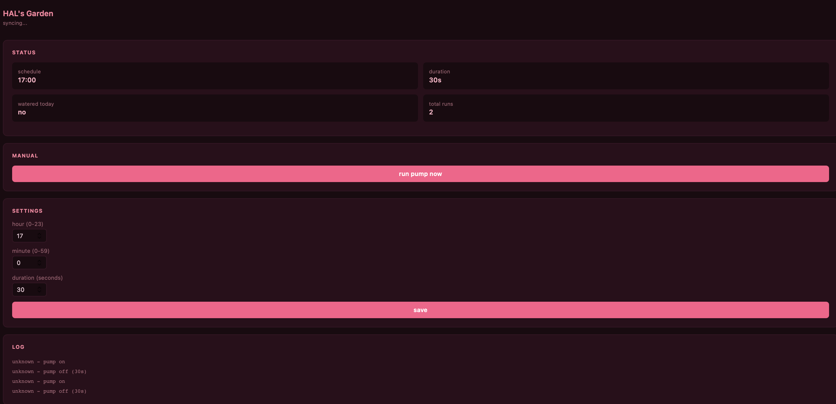
With NTP sorted, I added WiFi, time-based scheduling, and a web interface to the ESP32 firmware. The web UI lets me check the watering log, trigger the pump manually, and adjust the schedule and duration without reflashing. The ESP32 connects to the IoT network on boot, syncs time from the local NTP server, and handles the rest.
#include <WiFi.h>
#include <WebServer.h>
#include <Preferences.h>
#include "time.h"

#define RELAY_PIN 23

const char* ssid      = "YOUR SSID";
const char* password  = "YOUR PASSWORD";
const char* ntpServer = "Your NTP server";
const long  gmtOffset_sec      = -25200;
const int   daylightOffset_sec = 3600;

WebServer server(80);
Preferences prefs;

int waterHour    = 8;
int waterMinute  = 0;
int pumpDuration = 5;
bool pumpRanToday = false;
int  lastDay      = -1;

void saveSettings() {
  prefs.begin("hal", false);
  prefs.putInt("h", waterHour);
  prefs.putInt("m", waterMinute);
  prefs.putInt("d", pumpDuration);
  prefs.end();
}

void loadSettings() {
  prefs.begin("hal", true);
  waterHour    = prefs.getInt("h", 8);
  waterMinute  = prefs.getInt("m", 0);
  pumpDuration = prefs.getInt("d", 5);
  prefs.end();
}

void runPump() {
  digitalWrite(RELAY_PIN, HIGH);
  delay(pumpDuration * 1000);
  digitalWrite(RELAY_PIN, LOW);
}

const char PAGE[] PROGMEM = R"(<!DOCTYPE html>
<html><head>
<meta charset='UTF-8'>
<meta name='viewport' content='width=device-width,initial-scale=1'>
<title>HAL's Garden</title>
<style>
*{box-sizing:border-box;margin:0;padding:0}
body{font-family:system-ui,sans-serif;background:#fff0f5;color:#4a1030;padding:2rem 1rem;max-width:360px;margin:0 auto}
h1{color:#ff5c8a;font-size:1.2rem;margin-bottom:1.5rem}
label{display:block;font-size:0.8rem;color:#a04060;margin-bottom:3px}
input{width:70px;border:1px solid #ffb3c6;border-radius:6px;padding:0.4rem 0.6rem;font-size:0.9rem;margin-bottom:1rem;color:#4a1030;background:white}
button{background:#ff5c8a;color:white;border:none;padding:0.65rem 1.25rem;border-radius:7px;cursor:pointer;font-size:0.875rem;font-weight:600;margin-right:0.5rem}
button:hover{background:#e0336a}
.saved{color:#ff5c8a;font-size:0.8rem;margin-top:0.75rem}
hr{border:none;border-top:1px solid #ffb3c6;margin:1.5rem 0}
</style>
</head><body>
<h1>HAL's Garden</h1>
<form action='/save' method='GET'>
  <label>hour (0-23)</label>
  <input type='number' name='h' min='0' max='23' value='%H%'>
  <label>minute (0-59)</label>
  <input type='number' name='m' min='0' max='59' value='%M%'>
  <label>duration (seconds)</label>
  <input type='number' name='d' min='1' max='60' value='%D%'>
  <br>
  <button type='submit'>save</button>
</form>
<hr>
<form action='/water' method='GET'>
  <button type='submit'>water now</button>
</form>
%MSG%
</body></html>)";

void handleRoot(String msg = "") {
  String page = String(PAGE);
  page.replace("%H%", String(waterHour));
  page.replace("%M%", String(waterMinute));
  page.replace("%D%", String(pumpDuration));
  page.replace("%MSG%", msg);
  server.send(200, "text/html", page);
}

void handleSave() {
  if (server.hasArg("h")) waterHour    = server.arg("h").toInt();
  if (server.hasArg("m")) waterMinute  = server.arg("m").toInt();
  if (server.hasArg("d")) pumpDuration = server.arg("d").toInt();
  saveSettings();
  handleRoot("<p class='saved'>saved!</p>");
}

void handleWater() {
  runPump();
  handleRoot("<p class='saved'>done!</p>");
}

void setup() {
  Serial.begin(115200);
  pinMode(RELAY_PIN, OUTPUT);
  digitalWrite(RELAY_PIN, LOW);
  loadSettings();

  WiFi.begin(ssid, password);
  while (WiFi.status() != WL_CONNECTED) { delay(500); Serial.print("."); }
  Serial.println("\nhttp://" + WiFi.localIP().toString());

  configTime(gmtOffset_sec, daylightOffset_sec, ntpServer);

  server.on("/",      []() { handleRoot(); });
  server.on("/save",  handleSave);
  server.on("/water", handleWater);
  server.begin();
}

void loop() {
  server.handleClient();

  struct tm t;
  if (!getLocalTime(&t)) return;

  if (t.tm_yday != lastDay) {
    pumpRanToday = false;
    lastDay = t.tm_yday;
  }

  if (t.tm_hour == waterHour && t.tm_min == waterMinute && t.tm_sec < 30 && !pumpRanToday) {
    runPump();
    pumpRanToday = true;
  }
}
The ESP32 only supports 2.4GHz WiFi. If your IoT network is 5GHz only, it will not connect. Also - remove the Google Fonts import if your intranet has no internet access, or the page will take forever to load. Ask me how I know.
The Finish Line
It is mounted on the wall, drip emitters in nine pots across three shelves, water source on the kitchen table, electronics sealed in nested tupperware. It waters every day at 8am for five seconds. The web interface is pink. My plants are thriving and I have not touched a watering can in weeks.
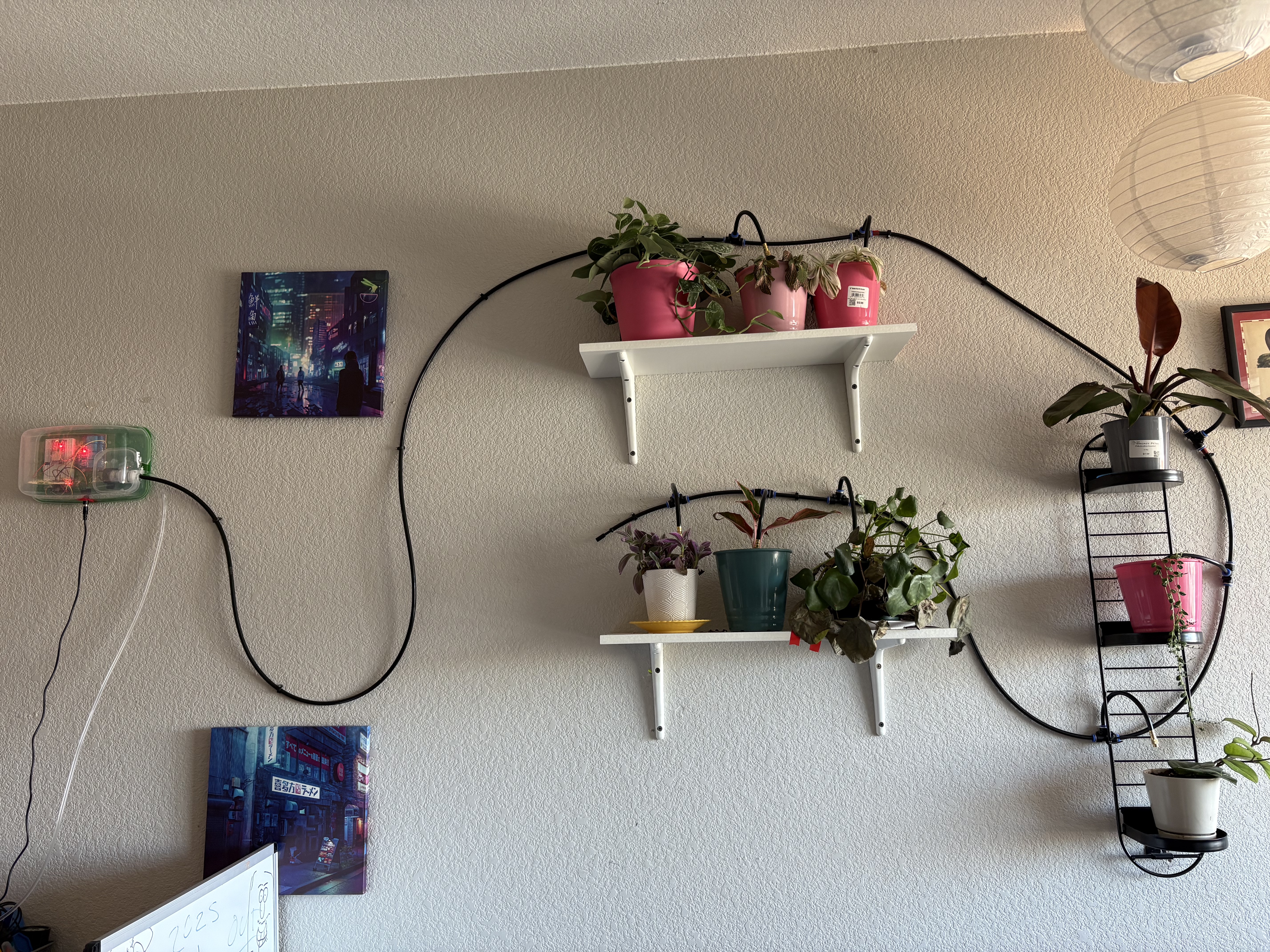
It is currently sitting on my wall, no longer judging me. Next steps: a flow sensor for actual water volume tracking, and possibly moisture sensors per pot so it only waters when needed. But that is a problem for future me, who I hear is very well-rested and enthusiastic about drilling more holes in tupperware.
Questions or corrections? Reach me at hello@nyxvia.com